Key Concepts
EnOS Model Management inherits the user and permission system of the EnOS Application Portal. Before starting, familiarize yourself with the relevant concepts of the Application Portal.
This file introduces the key concepts of model management.
Models
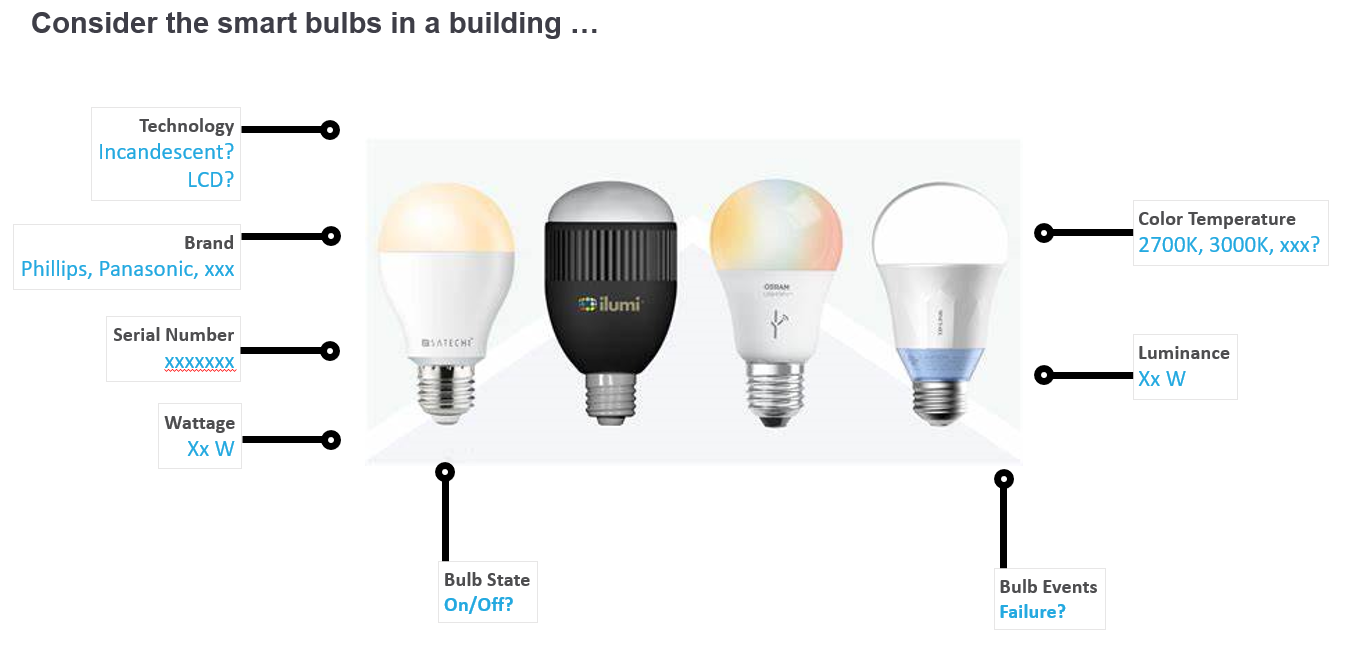
On EnOS, the primary function of a model is to abstract and standardize the properties and capabilities of business assets, as well as the logical relationships between these elements, for data analysis and application processing. Models focus on describing the business attributes and logical relationships of assets rather than the technical details of devices. For example, smart light bulbs, despite their differing specifications, share similar attributes, comparable functional logic, and identical types of collected data. An abstract model can standardize these properties of smart light bulbs. Models shield users from the diversity of devices, enabling them to focus on common characteristics of assets, which facilitates application development.
Besides representing an individual physical device, a model can also represent a physical site or container encompassing a series of devices of the same or different types. For instance, a wind farm is a physical site containing several wind turbine devices. Wind farms share common attribute categories, runtime data, and states, such as average wind speed and average power generation. The wind farm model includes generic business metrics like average wind speed and power generation without concerning itself with the specific parameters of each turbine.
By creating models, EnOS enables application developers to focus on business logic without being overly concerned about the heterogeneity of underlying devices. For example, an application monitoring electricity meters needs to record, process, analyze, and display data collected from actual meter devices. To describe electricity meter devices to an application, generic measurement points and processing logic of the meter must be abstracted, which can be achieved using models. Models transform the complexity of the real world into standardized, automation-oriented business entities, significantly enhancing the efficiency and flexibility of application development.
Components
A component is a reusable model that can establish reference relationships with other models. When a model is opened as a component, other models can reference its properties, even across groups, without group permission restrictions. Components can also be shared with other OUs to enable cross-OU referencing. When viewing the properties of a referenced component within a model, the property identifier is formatted as “component identifier: property identifier”.
Only models opened as components can be referenced. After being opened as a component, a model cannot contain other components.
Components already referenced by other models cannot be unpublished.
If a parent model is not opened as a component, its child models cannot be published as components.
When a parent model is opened as a component, newly created child models are also automatically published as components.
Model Types
In EnOS, models are categorized into two types based on whether they belong to the current OU: shared models and custom models.
Shared Models
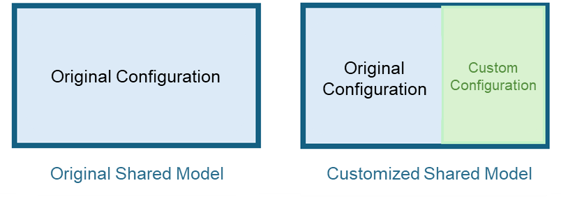
A shared model is a model created in another OU and shared with the current OU model, including key domain models accumulated by EnOS. Shared models are maintained by other OUs. Once a shared model is updated, it can be synchronized to the current OU from other OUs, depending on the update strategy configured during sharing. You can directly use the shared models provided by EnOS as device models. Alternatively, you can customize the configuration based on the original shared model to create a customized shared model for use.
In the Model menu under the Shared Models tab, you can view all shared models from other OUs available in the current OU.
Custom Models
A custom model is a model created within the current OU. If shared models do not meet your requirements, you can:
Create a custom model from scratch.
Clone or Inherit other models and customize the configuration.
Import models in bulk from other OUs.
Custom models are maintained by the current OU and can be shared with other OUs. After sharing, other OUs can view and use the model.
In the Model menu under Model Management, you can view all custom models created in the current OU.
Model Composition
A model consists of basic information, model elements, property rules, and model views, as shown in the following diagram.
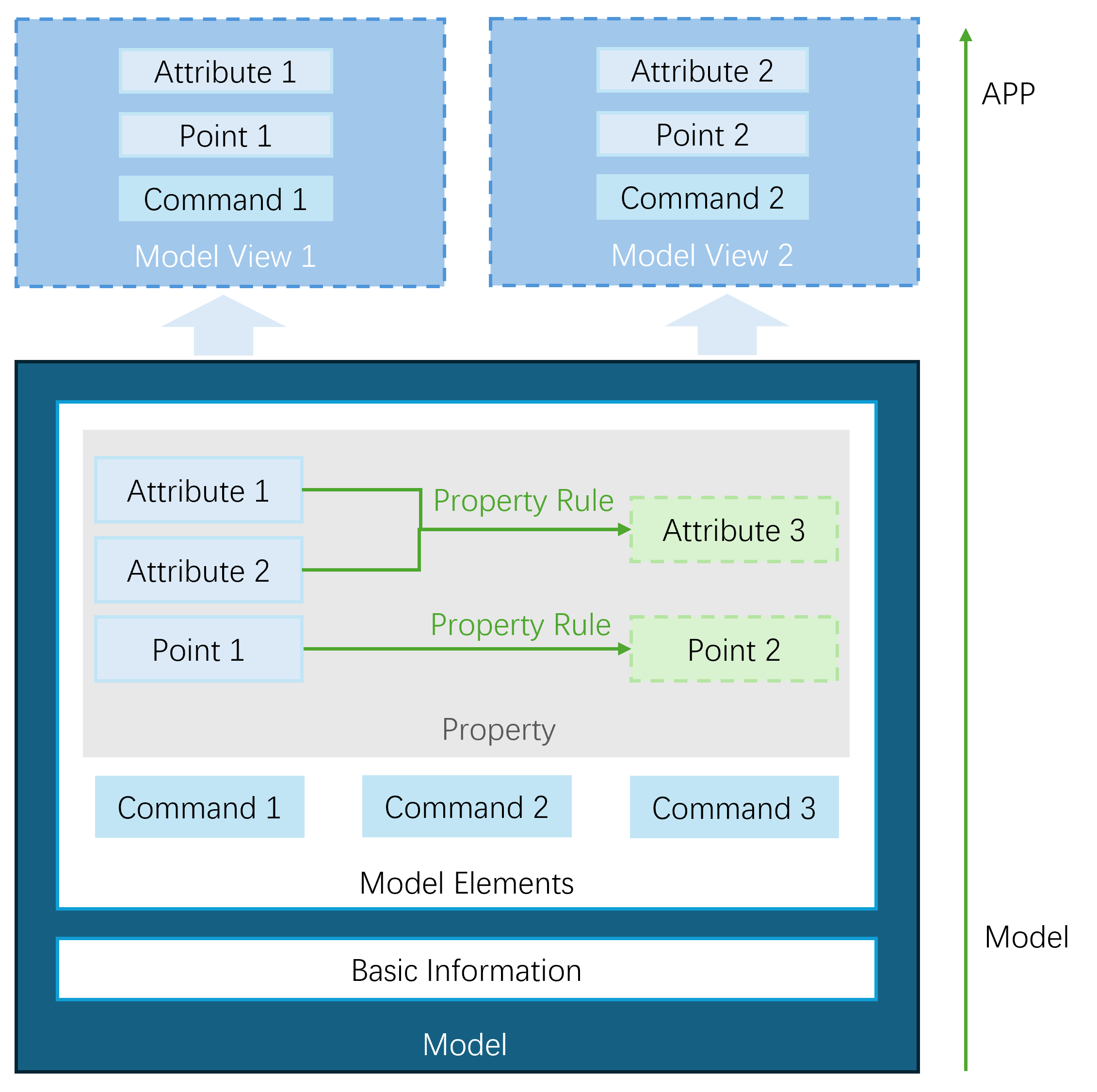
Model Elements
Model elements are primarily used to define what the device represented by the model is, what it can do, and what services it can provide externally. Model elements are divided into:
Property: Core elements describing the properties and status of a device, mainly including:
Attribute: Static feature information of a device, such as model type, installation location, and manufacturer.
Measurement Point: Real-time status data during device operation, such as real-time temperature, voltage, and cumulative power consumption.
Command: Capabilities or methods for remotely controlling and maintaining devices, such as remotely turning meters on/off or setting electricity consumption limits. Commands can have input and output parameters configured to enable more complex business logic.
Model elements within a model originate from:
Custom: Elements built directly within the model.
Reference: Elements referenced from the model element library.
Components: Elements derived from components already referenced within the model.
Inheritance: Elements inherited from a parent model.
For more information, see Configuring Model Definition.
Property Rules
Property rules define logical relationships between different model properties based on expressions. These rules are used to map property values within a single model or across multiple models, meeting the personalized needs of various business scenarios and improving model adaptability. For example, you can define property rules in the following scenarios:
Data mapping across model properties. For instance, the “total power generation” measurement point in a “wind farm” model is the sum of the “current power generation” data from all wind turbine devices within the wind farm. You can set this in the property rule as
Wind Farm. Total Power Generation = sum(Wind Turbines. Current Power Generation).Mismatch between raw device data and model property definitions. For example, the raw data format or units provided by a device may not match the model’s requirements, necessitating transformation and mapping through property rules.
Dynamic calculation of model properties based on multiple raw data measurement points. For example, the “range efficiency” measurement point in a car model may need to be calculated using the “maximum range” and “battery capacity” data. You can set this property rule as
Range Efficiency = Max Range / Battery Capacity.
For more information, see Configuring Property Rules。
Model Views
Model views allow users to selectively display certain model elements from a complete model based on different business needs, as well as customize the display order and names of model elements. A complete model may contain numerous attributes, measurement points, and commands, but not all elements are required in practical applications. Model views enable filtering and sorting of these elements, displaying only the key information needed by the application to enhance usability and readability. Additionally, model views support customizing the naming of model elements to align with business semantics. This improves end-user understanding and facilitates secondary development and integration of these model elements into applications.
For more information, see Configuring Model Views。
Model Management
Model management involves organizing, reusing, and controlling permissions for models, providing a foundational framework for managing and applying models.
Organizational Management: Models can be organized and applied scenically through model packages.
Reuse Management: Models and their elements can be reused and distributed through the model element library, model sharing, and model migration.
Permission Management: Permissions for models are controlled via model grouping.
Model Packages
A model package is a collection of models created based on usage scenarios. It defines the model elements for the devices or businesses within that scenario. Model packages simplify the model construction process, enabling users in various domains to quickly apply models to meet specific scenario requirements.
Model Element Library
The model element library contains all model elements accessible within the current OU, including those built in the current OU or shared from other OUs. Here, you can configure model elements for repeated use and reference them when configuring model definitions. The model element library helps users centrally manage model elements and enhances the efficiency of managing and using them.
Model Migration
Model migration refers to transferring models and model packages between environments using the Export/Import feature. You can export the models and related dependencies from the current environment as a ZIP package and import the package into the target environment to achieve environment-level model migration. Model migration supports cross-version and cross-environment deployment, enhancing the portability and reusability of models. When importing models, the system automatically handles dependencies between models to ensure proper functioning in the target environment.
Supports importing model files exported from EnOS Device Connection and Management (DCM).
Supports importing 3.X model files exported from EnOS General Data Service.
Supports importing custom configurations for shared models.
Before migration, ensure that the current account has permissions to export and import models. For more information, refer to Model Management Permission Allocation。
Model Groups
A group is a unit for managing permissions on models and model packages. You can only add, delete, or modify models within a group if you have the corresponding group permissions. Grouping isolates models, ensuring no data conflicts between groups, which aids in controlling data permissions. In model management, groups can be categorized based on whether a single OU manages them:
Standard Group: Requires specifying a developer OU. Models in the standard group are created and managed within the developer OU and can be shared with other OUs, where they can be viewed and used. For example, a Solar group could be created for the photovoltaic domain, developed and updated in the developer OU, and shared with designated OUs.
Built-In Group: Each OU can view, create, and manage models in built-in groups. Built-in groups are further classified based on cross-OU visibility:
Custom Group (Custom): Custom groups created within the current OU are restricted to being viewed and used within the current OU. These groups cannot be shared with other OUs, functioning as private models within the OU.
Default Group (Default): Default group models created within the developer OU can be shared with other OUs. Default group models created within other OUs are only visible and usable within the current OU. These groups are typically used to manage legacy models from EnOS 2.X. Applications developed based on EnOS 2.X can directly read models within these groups without modifying any configurations.
Model identifiers include the group identifier and model version number, ensuring uniqueness within the same group. The format is: A:B:C:D.
A: Identifier of the standard the model follows, defaulting to
dtmi.B: Identifier of the associated group.
C: Business identifier (user-specified). Models in different groups can have the same business identifier.
D: Version number, defaulting to 1.
Model Relationships
Models can have relationships of Clone, Inherit, and Reference.
Clone
Models created based on the Clone mode. The newly created model has identical model elements to the cloned model, but the two models are entirely independent, with no mutual impact from changes. Clone is primarily used to quickly create similar models with minor modifications.
Inherit
Models created based on the Inherit mode. The newly created model is defined as a Child Model, and the inherited model is defined as the Parent Model. Inherit is mainly used to extend existing models to create new ones. Key properties of this model relationship:
The child model inherits all elements of the parent model; inherited elements cannot be modified.
Child models can be inherited further, supporting multi-level inheritance.
Changes to elements in the parent model are synchronized with the elements of the child model inherited from the parent model, maintaining consistency with the parent model.
Child models can have their independent elements. If a newly added element in the child model has the same identifier as an element in any parent model, the parent model’s element will override the child model’s.
Reference
The reference relationship includes a model referencing another model (component) and a model referencing existing elements.
Reference Components in a Model
When configuring a model to reference another model that has been opened as a component, the two models establish a Reference relationship. The referenced model is called the Component, and the model referencing the component is referred to as the Main Model. Key properties of this model relationship:
After the main model references a component, all model elements in the component are incorporated into the main model.
Model elements referenced from the component cannot be modified in the main model.
A component can be referenced by multiple models and can also be referenced by models in other groups.
When elements in the component change, the referenced elements in the main model are updated synchronously to remain consistent with the component.
Reference Elements in a Model
When adding elements to a model by referencing elements from the model element library, a Reference relationship is established between the model and the referenced elements. The referenced element may come from another model or be created directly in the model element library.
Referenced elements cannot be modified in the model.
Elements can be referenced by multiple models but cannot be referenced across groups.
When an element is updated, the changes are synchronized to the model.